
One of the key features of UHPC is its ability to create multiple microcracks closely spaced to each other under certain conditions. This is the so-called multi-microcracking process that characterises strain-hardening materials, i.e. those materials that are able to hold a constant stress throughout a crack even at high strain values. However, one may consider that multi-microcracking is not a property of UHPC, i.e. a material property, but a property of the structure made with it. It means that even though we have obtained a strain-hardening behaviour in lab conditions using standard specimen and tests methodologies, it is possible that our designed structure behaves as a strain-softening one. Why is that? The answer is found in the fact that development of strain-hardening process in a structure mainly depends on (i) the nature of forces acting on it and (ii) fibre orientation inside the element which may differ a lot depending on element thickness and pouring system. Therefore, even though UHPC shows a strain-hardening behaviour under standard lab conditions, we need to know in which situations we can consider it or not in design. In this post we show a structural application in which consideration of strain-hardening behaviour is not only possible but a also a must to predict its real behaviour. Do you want more info? Keep reading 🙂
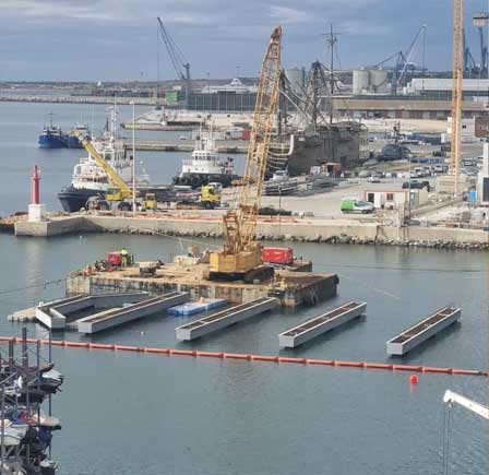
The structural element we are talking about is a 35-mm thick slab made of UHPC without any rebar (just fibres) simply suppported along its edge with only an upward restriction subjected to a vertical uniform loading. The slab tested was 3.20 m length and 2.30 m width. Relative displacement from mid-span to one support edge was recorded. Test setup is shown in the following picture.

When dealing with fibre reinforced concrete it is completely necessary to define both nature of loading and support conditions as they determine stresses pathways. Note that fibre-reinforced concrete is not an isotropic material when using a common fibre amount of 2% in volume, so its strength may vary from one point to another and also according to the direction of principal stresses. Making a good calculation seems to be a tough thing :/
So then, what is the material behaviour whe should use for its design? Probably, the most practical thing to do is to consider that material properties are the same in the whole element despite the anisotropic nature of UHPC. Its characteristic strength may be obtained from standard characterisation tests. Then, there are two factors left to be considered: (i) fibre orientation coefficient and (ii) safety factor. As this specific slab is a redundant structure which requires the formation of multiple macrocracks to reach its maximum capacity, it seems convenient to use a global fibre orientation factor. Partial safety coefficients may be obtained from NF P18-710 (UHPC French standard).
In this particular case the crack pattern expected at failure is shown in the following picture (left). If UHPC behaved as a strain-hardening material, several micro-crack would appear before a single one became a macrocrack (right). What is the effect of this microcracking process? (i) A reduction of crack width in Service Limit State as the overal strain is smeared in several cracks instead of one; (ii) higher ductility up to maximum load; and (iii) higher strength.

The loading process was carried out by using 700 kg weight concrete blocks. It had a little inconvenience: it was impossible to uniformly distribute the load of each block on the whole slab. That is why it was impossible to obtain a smooth and good looking uniform load vs displacement at mid-span curve 🙁
Following picture shows the slab with 16 concrete blocks on it. A total weight of around 11 Tons. Quite a lot for a 35-mm thick slab !!

Three numerical model were also carried out using two different constitutive behaviour hypotheses in tension: (i) average consitutive behaviour obtained from a previous UHPC characterisation using prismatic specimens tested under four-point bending tests; (ii) design tensile behaviour (characteristic behaviour modified by a global orientation factor and partial safety coefficients); and (iii) a UHPC without fibres (with a pronounced softening behaviour). Results from these models and real behaviour obtained from the test are compared in the following picture, showing the good approach obtained and the suitability of the design process.

After finishing the test, all concrete blocks were taken away and the underside of the slab was examined to see the cracks. The following movie, despite corresponding to a different test of a more slender slab, gives you an idea of the loading process followed, and explains why the uniform load versus diflection at mid-span curve obtained has such a twisty shape 🙂
Surprisingly, just one single crack appeared when we turned over the slab. It was a clearly visible macrocrack. There was no sign of any microcrack. Yet, we know they were there 😉 Next step was watering the surface so as water could fill all microcracks. After that, we dried up quickly the surface and took this beautiful picture.

This picture shows the strain-hardening behaviour of UHPC in this specific element under specific loading and support conditions. Principal stresses pathways can be clearly seen as well as microcrack spacing differences in different areas due to the anisotropic nature of UHPC. However, despite that anisotropy, numerical model developed considering UHPC as a isotropic material was accurate enough to reproduce its response.
We hope you find this experience on UHPC interesting and don’t forget to subscribe to our blog !!


3 Responses
Good! But, why don’t you use water? You could be able to control the load much better and you can load the entire slab!
That was Plan A 😉 We wanted to use either water tanks or pools. However due to the short time we had for testing, we had to use concrete blocks 🙁 It was much faster! Think that we just wanted to check the microcracking process and the suitability of the design and pouring procedure followed. I think we’ve got that.
Many thanks for this excellent article.
FIBRAFLEX amorphous metallic fibers are fully relevant to control microcracks. Would you like to know more, feel free to get in touch with me at any time !
Best regards.
Florian BERNARD
Comments are closed.